. image of the sprite table from Computer Intro manual
. notes on glitch/circuit bending a Magnavox Odyssey 2
. Magnavox Odyssey 2 glitch/circuit bending notes
. 2014.12 - initial notes...
. video : video of Odyssey 2 glitching
. the Odyssey2 (aka the Phillips Videopac outside of the US) is a great system to generate classic 8-bit glitch video due to the 64 built in sprite graphics as well as the 9 x 8 background grid. when glitched, the system rapidly draws the sprites, background and grid in different colors.
![]()
. image of the sprite table from Computer Intro manual
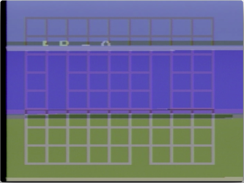
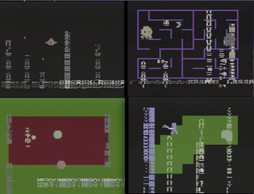
. still frame from glitch capture showing background grid
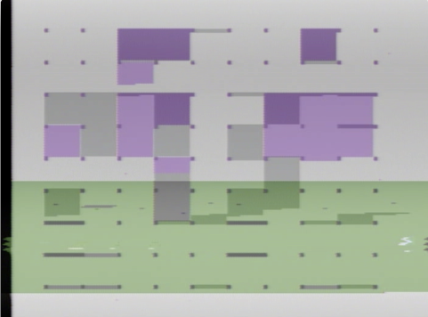
. still frame from glitch capture showing background grid and partial sprite graphics
. however, when the system is glitching - the screen is redrawn quite fast. here are nine sequential frames from a glitch capture
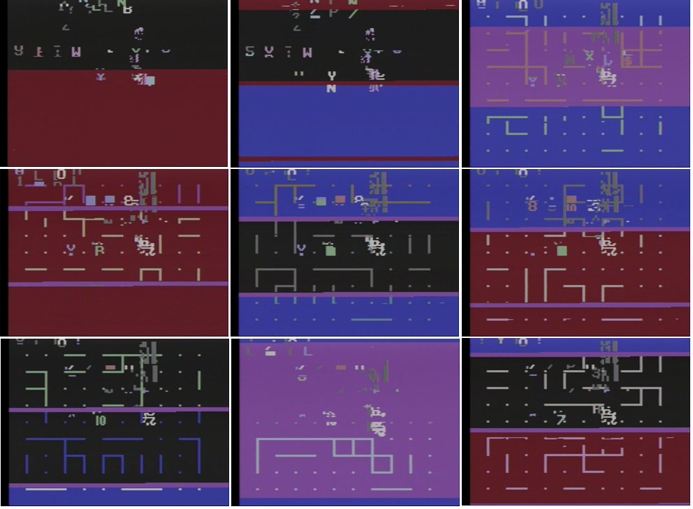
. you can make out a few of the system sprites and partial system sprites in these captures as well as an ever changing background grid layer.
. basic sprite colors (captured from O2Em )


. so, how did i get into circuit bending an odyssey 2 ?
. i had an Odyssey 2 laying around and was inspired by other artists bending classic Nintendo and Sega video game systems.
. the first step was to convert the video to standard NTSC, so i followed this guide
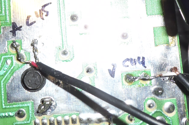
. audio out is C45 (capacitor 45) and video out is C44
. i connected my 100M resistor and alligator clips to the ground pin under the 'C' in C45.
. however, something didn't quite work as intended... lower pitched sounds caused the graphics to glitch. you might have noticed the 'SELECT GAME' logo looking a little scrambled in the video when the system was started up.
. and it affected other games when they made sound :
. so, it was already headed in the right direction.
. next, i scoured the web for Odyssey 2 forums, schematics, service manuals, etc and found a wealth of information on how everything was put together. i kept a folder of bookmarks to keep the information together. some of the most useful sites were:
. Videopac / Odyssey2 message board
. Great overview of the Odyssey 2 hardware
. invaluable resource for actual hardware chips
. emulator, compiler and programming reference
. long story short - the information was helpful in helping me understand what i was seeing, but a few random connections really got things going...
. standard disclaimer - be careful when you are working w/powered electronic equipment (especially when it's plugged into the wall) you can damage the equipment and/or yourself ! proceed at your own risk !!
. the O2 is sitting w/the keyboard facing downward to expose the circuit connections:
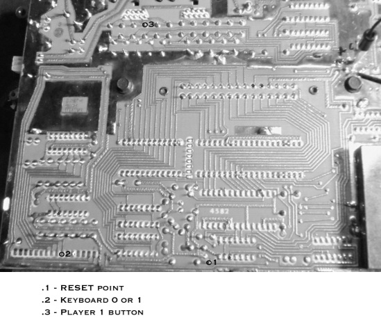
. so i took a picture, converted it to grayscale and enlarged it to an 8.5" x 11" printout to make notes on which pads worked or did something interesting...
. i connected my 100M resistor and alligator clips to the ground pin under the 'C' in C45. (upper right of the photo) and used that to touch various solder points.
. the RESET point (at location o1 ) when connected to 100R -> GND would reset the system
. when resetting the system, listen for a full start up beep to make sure it was a clean reset
. location o2 would start the game (by triggering a key press)
. location o3 would trigger player one button press (the other pins in that area map to other joystick actions)
. after a little time experimenting on over six different cartridges - i found one chip that gave the most consistent glitching w/o freezing the system was IC3:
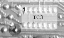
. the darkened circle is the RESET point (o1 in the image above)
IC3 : SN74LS32N or 612194-1 : Quad 2-input OR gates
: PIN 1 shown
: PINS 2,3 worked the best
. so, those are my hastily thrown together notes to better describe and document my Magnavox Odyssey 2 process and discoveries.
-james
(a nomad. )